Discussion:
[OpenSCAD] Unwanted lines in the wireframe view
mannifold
2018-11-24 18:19:46 UTC
Permalink
Hi everyone! I'm working on a project where I make simple models of houses. I
want a wireframe view of the tops of the houses to make a site-plan-esque
drawings.

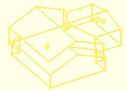
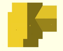
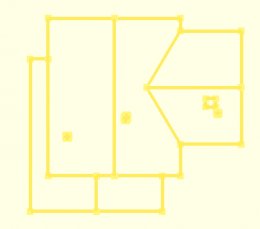
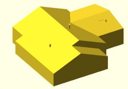
However, I've run into a problem with the wireframe view in the form of some
unwanted lines:
<Loading Image...>
<Loading Image...>
<Loading Image...>
<Loading Image...>

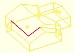
If you look closely at the view with surfaces vs the wireframe view, you can
can probably see that these lines are the unwanted ones:
<Loading Image...>
<Loading Image...>

Is there any way to make the wireframe view look like this?
<Loading Image...>

If it helps, I've built this house out of pieces that look like this:
<Loading Image...>
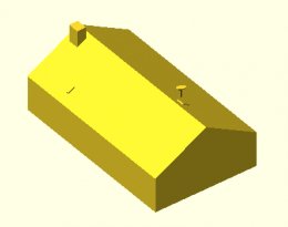
I make the houses by rotating and translating a bunch of these pieces
together. I made the house in question by calculating exactly the right
amount to scale and translate three of the pieces together to make the shape
you see, but it's interpreting that single surface on the left as two
surfaces. Any help is greatly appreciated. Thanks in advance!


--
Sent from: http://forum.openscad.org/
shadowwynd
2018-11-24 19:39:57 UTC
Permalink
Without seeing the code, my first guess would be that it looks like two
pieces because it is two pieces.

Even if the pieces are very close together, they may still be separate. You
could try wrapping the pieces together in a union:

union()
{
part1();
part2();
}

otherwise, post the minimal code needed to show the problem and some of the
people here can have a look.


--
Sent from: http://forum.openscad.org/
corpsman
2018-11-24 20:31:17 UTC
Permalink
Hello List,

Meanwhile i did a lot of things with OpenSCAD, but what is really
puzzling me, if it is possible to do things like this handle

https://www.thingiverse.com/thing:2943379

The bracket was no problem, but what is about that curve part. Can
anyone show how things like that are done, or is something like this not
possible with OpenSCAD ?

Corpsman
Parkinbot
2018-11-25 00:48:55 UTC
Permalink
better open a new thread if your post doesn't refer to the current thread.
MichaelAtOz can you do the shift?

To answer your question: If you use the right tools and handle them
properly, curvy things with fancy shapes are well possible in OpenSCAD. See
my sketchy code doing a handle similar to the one you referred to. I used a
technique that leads into the world of point lists where affine operations
are implemented as functions. It comprises an interpolation scheme named
nSpline() from the splines.scad lib, one or more shape generator schemes an
extrusion path scheme which have to be individually implemented and the
extrusion scheme sweep() from the Naca_sweep.scad lib. Follow the link to
download these libraries.

To see what happens you can cautiously play around with the values of A.
Each row of A (and B) is a parameter set that is interpreted by handle() and
describes a key slice and its positioning in 3D. As commented in the line
above A, a slice is defined by two radii used in the oval() call, a rotation
around the y axis, and a translation along x and z. The interpolation scheme
interpolates the key slices sequence into a much more refined sequence.
oval() returns a point list, T_ and Ry_ operate over it, and sweep()
consumes the list with the slices and does all the dirty work needed for
extrusion and the final polyhedron call.

<Loading Image...>

use <naca_sweep.scad> // https://www.thingiverse.com/thing:1208001/files
use <splines.scad> // https://www.thingiverse.com/thing:1208001/files

//parameters to be interpolated and interpreted by handle()
// r R rot_y, x, z
A = [
[10, 28, 0, -100, 0],
[ 6, 18, -45, -95, 30],
[8, 8, -90, -70, 40],
[10, 10, -90, -65, 40],
[15, 15, -90, 0, 40],
[10, 10, -90, 65, 40],
[8, 8, -90, 70, 40],
[ 8, 18, -135, 95, 30],
[10, 28, -180, 100, 0],
];

B = nSpline(A, N=100); // interpolation

sweep(handle(B)); // extrusion

function handle(A) = let(N = len(A))
[for(i=[0:N-1])
T_(A[i][3], 0, A[i][4], // translate
Ry_(A[i][2], // rotate
oval(r=A[i][0], R=A[i][1])))]; // shape function

function oval(r = 10, R=20, N = 60) =
let(N_ = 2*ceil(N/2), c = circle(r, N=N_), off = (R-r)/2)
[for(j=[0:N_-1]) let(o=j<N_/2?off:-off) [c[j][0], c[j][1]+o, 0]];

function circle(r=10, N=30) = [for(i=[0:N-1]) r*[cos(360/N*i),
sin(360/N*i)]];


--
Sent from: http://forum.openscad.org/
stonysmith
2018-11-25 01:00:51 UTC
Permalink
Many things are possible. Some are not easy. :)

There are literally thousands of ways to approach this.
Here is a quick approximation of the curved part of the handle.


$fn=32;
intersection(){
minkowski(){
difference(){
cylinder(d=8,h=3,center=true);
cylinder(d=6,h=10,center=true);
translate([4,0,1.25])rotate([0,10,0])cube([15,15,1],center=true);
translate([4,0,-1.25])rotate([0,-10,0])cube([15,15,1],center=true);
}
sphere(d=2,center=true,$fn=32);
}
translate([3,0,0])cube([6,12,12],center=true);
}


--
Sent from: http://forum.openscad.org/
mannifold
2018-11-25 02:39:13 UTC
Permalink
shadowwynd,

The model shown is already the result of a union. I would suppose that a
union would've eliminated those lines but for some reason it hasn't. I'll
post some code when I get a chance, but for now, know that each house piece
is a polyhedron, and the house itself is a union of those polyhedrons.

As for the other replies, I have no idea what they're talking about
¯\_(ツ)_/¯


--
Sent from: http://forum.openscad.org/
Carsten Arnholm
2018-11-25 12:03:37 UTC
Permalink
Post by mannifold
Hi everyone! I'm working on a project where I make simple models of houses. I
want a wireframe view of the tops of the houses to make a site-plan-esque
drawings.
However, I've run into a problem with the wireframe view in the form of some
<http://forum.openscad.org/file/t2406/iso_solid.png>
<http://forum.openscad.org/file/t2406/iso_wireframe.png>
<http://forum.openscad.org/file/t2406/top_solid.png>
<http://forum.openscad.org/file/t2406/top_wireframe.png>
If you look closely at the view with surfaces vs the wireframe view, you can
<http://forum.openscad.org/file/t2406/iso_wireframe_highlighted.png>
<http://forum.openscad.org/file/t2406/top_wireframe_highlighted.png>
Is there any way to make the wireframe view look like this?
<http://forum.openscad.org/file/t2406/top_wireframe_fixed.png>
OpenSCAD is fundamentally a solid modeller, i.e. models described as
surface meshes. The "wireframe" view shows you the contours of the
resulting polyhedron faces after boolean operations, but before
tesselation of faces into triangles (STL contains only triangles).

Compare OpenSCAD wireframe views of

cube(20);
translate([5,5,0])cube(20);

versus

cube(20);
translate([5,5,0.0001])cube(20);

You will see a similar effect to what you are describing. The difference
is that the top and bottom surfaces are not perfectly flush in the
second example.

I suspect the same happens in your case. Since the roofs are not
parallel to any global axes, there is a numerical uncertainty in the
exact roof angles, as the two houses are computed from different
coordinates. The result is that they have slightly different roof angles
and/or the top roof is slightly offset +Z from the other. This leads to
the same effect as with the cubes above.

Carsten Arnholm
mannifold
2018-11-25 19:34:43 UTC
Permalink
cacb,

Does this mean that it would be impossible for me to make the roof surfaces
perfectly flush and eliminate the unwanted line?

I calculated (with math!) the exact amount of translating that /should/ make
the roofs flush, but yeah it looks like program is interpreting them as
not-perfectly-flush.


--
Sent from: http://forum.openscad.org/
Parkinbot
2018-11-25 21:46:24 UTC
Permalink
mannifold,

nothing is impossible. It mainly depends on how you construct your solid.
With a global union you easily run into numerical problems, so better avoid
it. If start carving out your house from a large cube in a subtractive
fashion (using a large global difference), you won't see such lines, at
least if you further avoid numerical problems by using oversized
subtrahends. See the following code pieces, which are semantically
equivalent.

rotate([10, 0, 0]) cube(20);
rotate([10, 0, 0]) translate([5,5,0])cube(20); // perfectly calculated, but
no match

use global difference with exact subtrahends

rotate([10, 0, 0])
difference ()
{
cube([25, 25, 20]);
translate([20,0,0]) cube([5,5,20]);
translate([0,20,0]) cube([5,5,20]);
}

even this can cause problems, e.g. when the rotation is applied separately
to each primitive.

difference ()
{
rotate([10, 0, 0])
cube([25, 25, 20]);
rotate([10, 0, 0])
translate([20,0,0]) cube([5,5,20]);
rotate([10, 0, 0])
translate([0,20,0]) cube([5,5,20]);
}


all this doesn't happen with oversized subtrahends

difference ()
{
rotate([10, 0, 0])
cube([25, 25, 20]);
rotate([10, 0, 0])
translate([20,-1,-1]) cube([6,6,22]);
rotate([10, 0, 0])
translate([-1,20,-1]) cube([6,6,22]);
}


--
Sent from: http://forum.openscad.org/

Loading...